GeoServer and ORACLE – WFS & WMS Config Tips

This post is a brief description of my findings on setting up Geoserver from scratch and some particular points on setting it up for an Oracle connection. I hope it will prove useful for others.

INSTALLATION
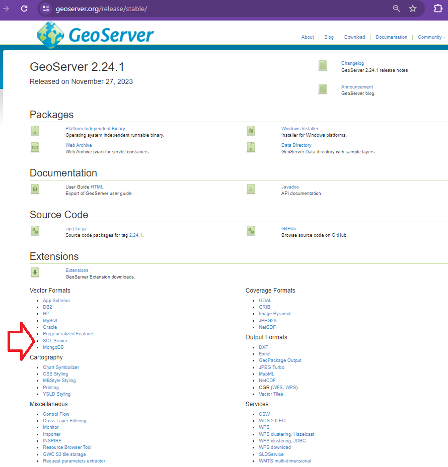
GeoServer with ORACLE database connection support
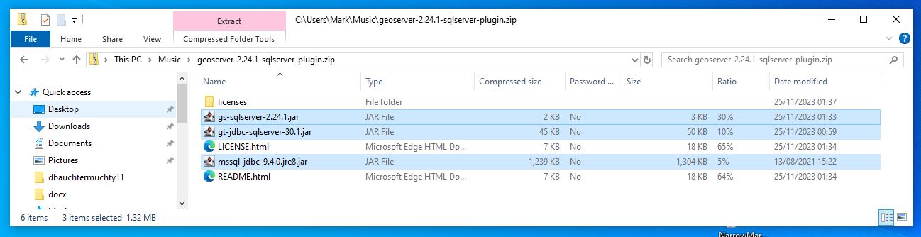
Geoserver Postgres (PostGIS) connection support comes with the default installation. This is NOT the case for Oracle or SQL Server therefore for enterprise purposes it is a requirement to install Geoserver WITH Oracle and SQL Server extensions if you wish to support these database connections.

I’ve done a post on Geoserver on windows installation link here that talks specifically about SQL Server. I will not go into a lot of detail about installation here. See below for links to the geoserver docker image I didn’t install the geoserver I describe here but I can confirm that we have been successful in including Oracle as a plugin to our Geoserver installation and we are able to connect.

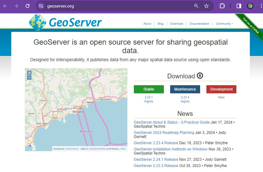
Official Geoserver Docker Image GITHUB

Below is a recent (Feb 2024) list of Docker parameters available at install including Oracle and SQL Server please seek advice on the use of Docker for installation if you are not familiar with it already.

GENERAL SETUP

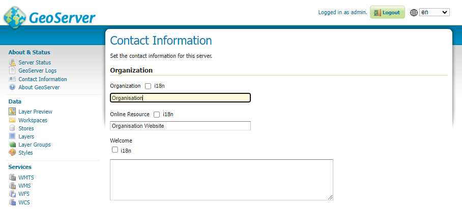
Contact Information – General Setup
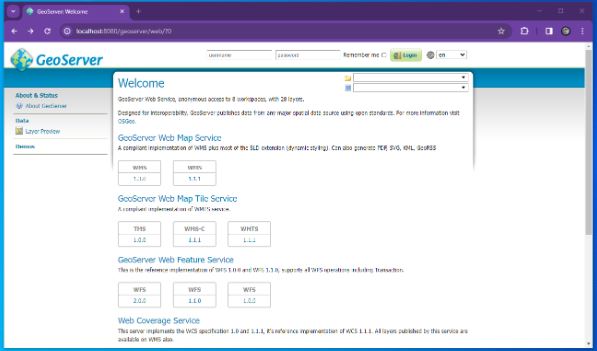
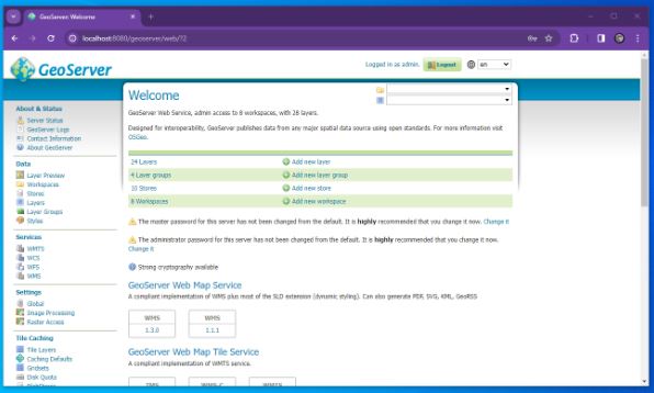
On the Welcome screen there is a line that reads For more information visit {organization} to change this from the initial meaningless variable setting go to Contact Information and fill out your organisation.

Difference between Save and Apply – General point

In geoserver admin there are a lot of pages where there is a Save and an Apply button. Most users initially at least find this confusing.

In GeoServer, the terms “Save” and “Apply” serve different purposes:

Save:
When you click “Save”, it permanently stores the changes you’ve made to the configuration. These changes are saved in the GeoServer configuration files. , “Save” ensures that your modifications persist even after restarting GeoServer or rebooting the system. It’s like committing your changes to a version control system—it makes them permanent.
Apply:
“Apply”, on the other hand, is more immediate. When you click “Apply”, it takes the current configuration (including any unsaved changes) and applies it dynamically. The applied changes take effect immediately without requiring a restart or permanent storage. Think of it as a temporary adjustment that affects the running instance of GeoServer but doesn’t alter the saved configuration. In summary, “Save” makes changes permanent, while “Apply” applies them immediately without saving them to the configuration files

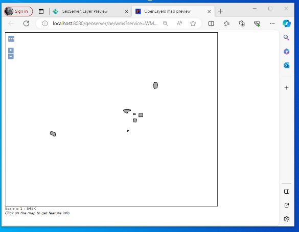
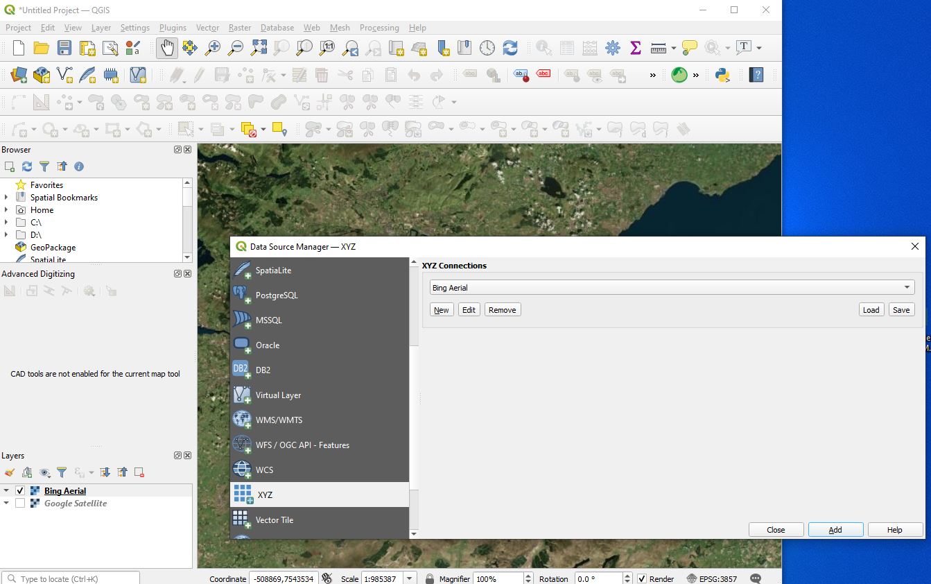
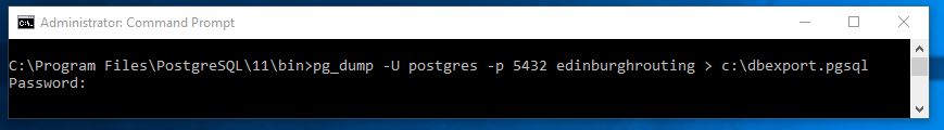
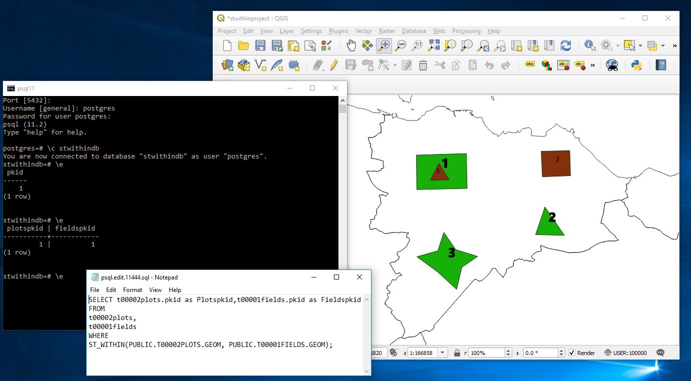
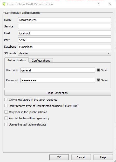
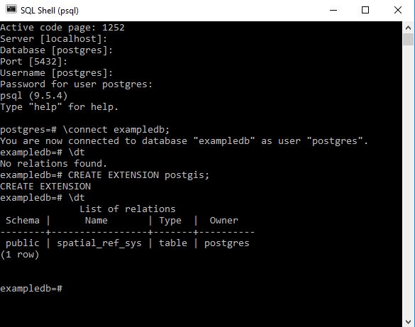
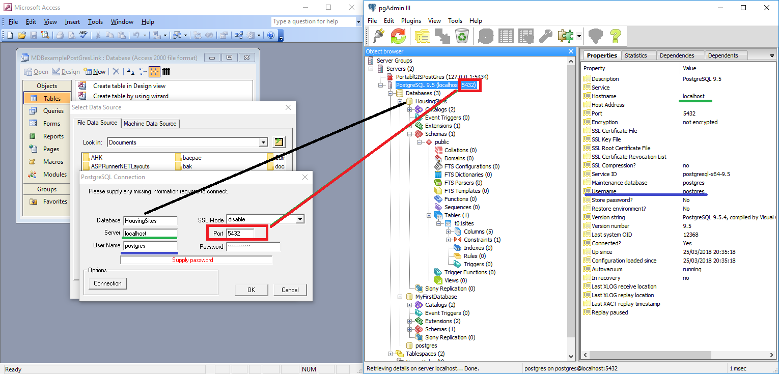
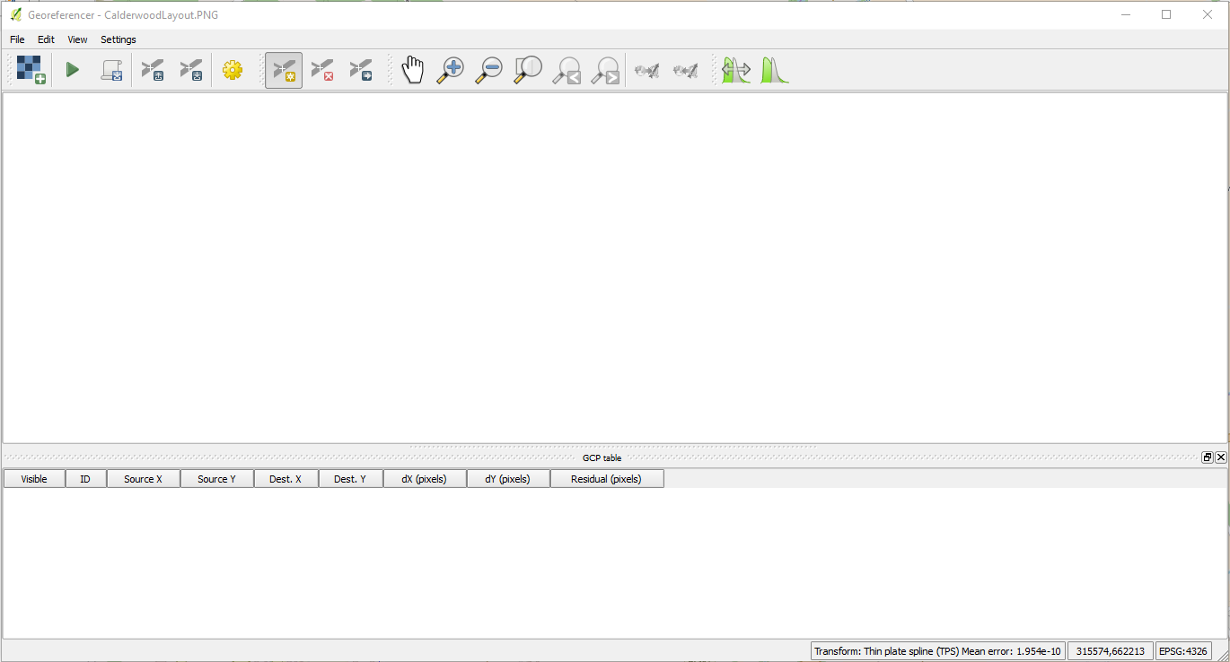
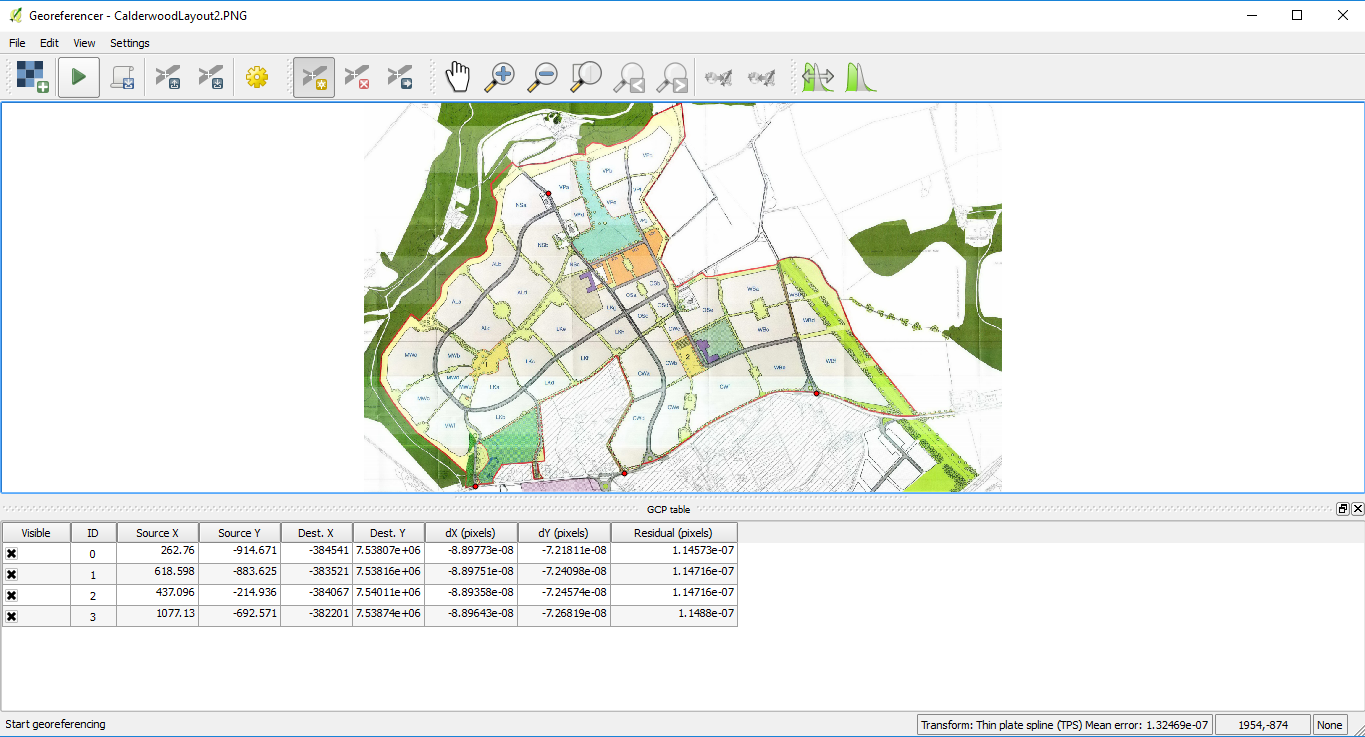
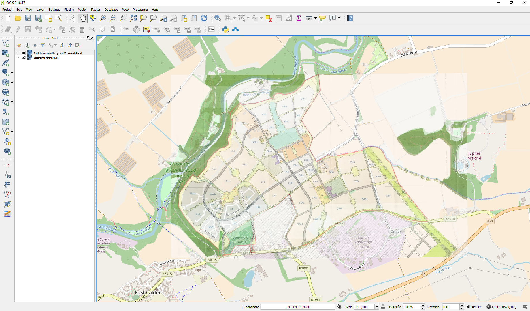
The first thing you will want to do is determine if you can actually connect to your ORACLE database.

ORACLE required parameters for database connection. Before you continue make sure you have the following

ORACLE host name
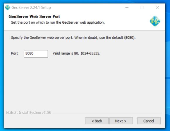
Port ORACLE database (default 1521)
database name
user – case sensitive
password – case sensitive
Geoserver installed with Oracle extension

It is good idea to get your DBA to setup a read only user if you are connecting to a database that is part of a vendor supplied product as you really should not be editing the database through anything except the vendor’s UI and Geoserver can be setup to allow edit of data. Geoserver has powerful security configuration included but conflicting settings can arise that may alter the intended security levels making it safer to enforce read only least privilege at the database level.

ORACLE and Postgres – some SQL Differences
Please be aware Oracle databases are by default case sensitive but may convert SQL Strings to upper case when passed to Oracle. I believe this complies strictly with the SQL Standard.

Postgres classifies tables, columns views and other database objects as Identifiers. SQL Identifiers must begin with a letter. If possible avoid including special characters in the naming of identifiers because although postgres may support them special characters are not allowed in the SQL Standard so their use might render applications less portable. Additional identifiers and keyword must begin with a letter. Keywords are defined as items such as SELECT / UPDATE / CREATE etc.. The SQL Standard says that databases should not define a key word that contains a digit or starts or ends with an underscore so identifiers could be something like t001users should be safe against possible conflict with future extensions of the standard. In postgres the maximum identifier length is 63 bytes. Additionally Postgres also folds unquoted names to lower case but some postgres management UIs allow for the naming of identifiers with varied case.

UPSHOT for Geoserver (and anything else for that matter)

If you are having difficulty referencing tables or views in any enterprise database – experiment with the case sensitivity in the query. There might be some folding of object names when passed to the server.
This characteristic should be born in mind when using SQL Views in Geoserver.

ORACLE Store setup to get the most out of Geoserver
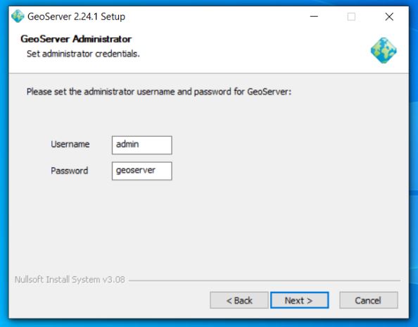
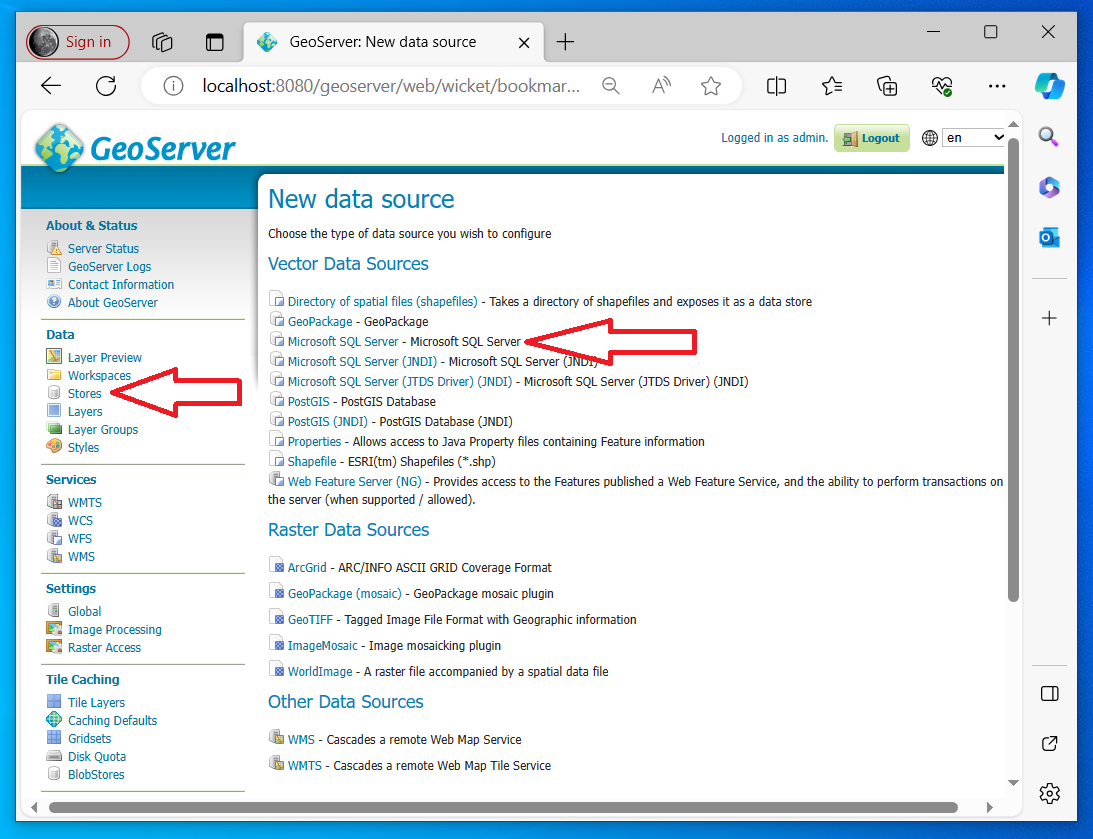
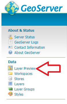
Login to Geoserver admin panel using your admin account

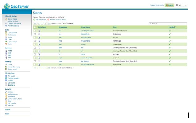
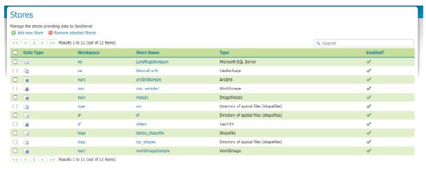
On the left hand side under Data hit Stores

Assuming you have successfully installed Geoserver with the Oracle extension you should be presented with the following dialog and in particular the items highlighted below.

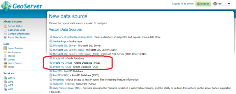
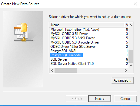
Oracle NG uses a standard Oracle driver (ignore the other options this article will not explain them)

Select Oracle NG

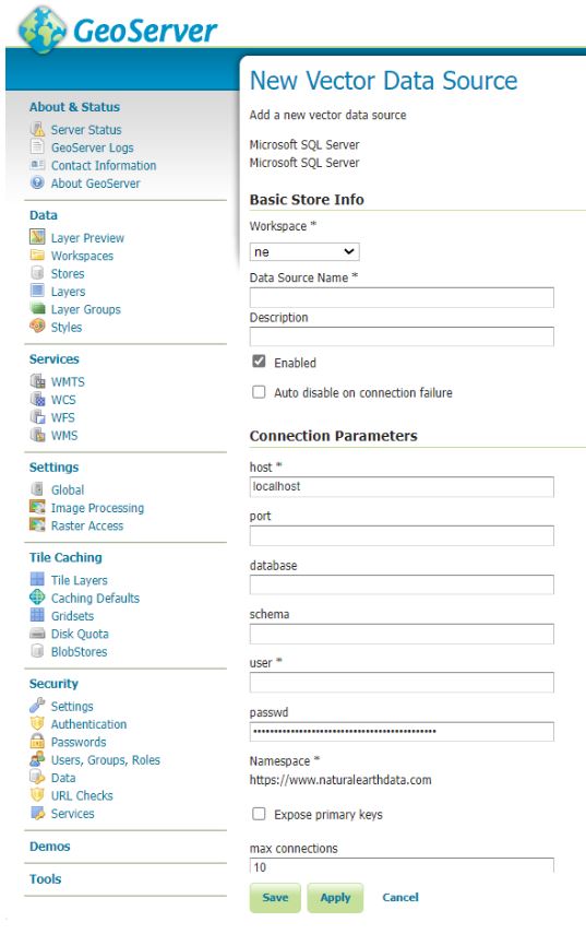
Use the default settings for most things but IMPORTANTLY ensure Expose Primary Keys is ticked

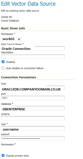
NOTE from our brief testing we found that exposing primary keys seemed to be one factor that improved stability in our Oracle connection when dealing with QGIS.

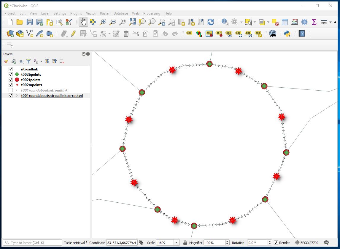
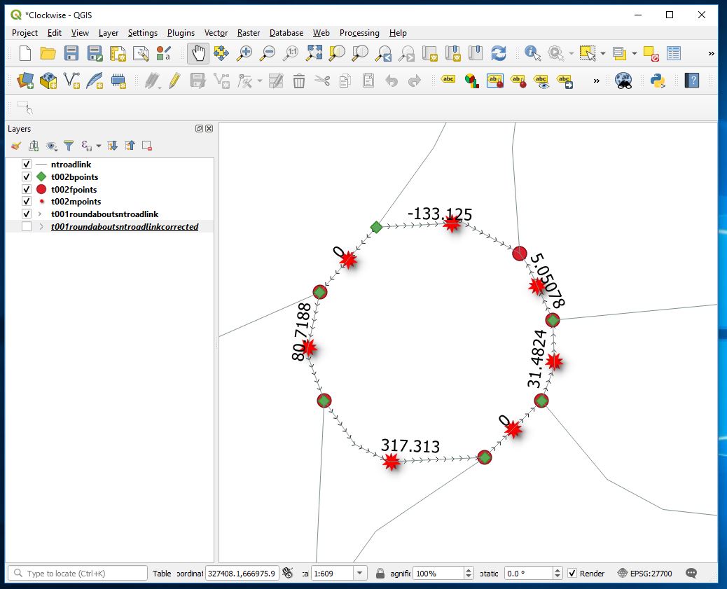
QGIS WFS set up to improve Oracle Connection Stability
It is recommended that you have a copy of QGIS to test setup to things like WFS

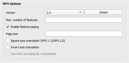
When we first started displaying specifically the Oracle spatially enabled table in QGIS via WFS service we found that the layer would initially display but if we were to leave the project and go back in for a period of time the layer would not be visible. This seemed to be temporary and after an unpredictable amount of time the layer would reappear. The attribute table continued to be viewable but polygons were not visible.

We fixed this by ensuring Expose Primary Key (see Geoserver layer configuration) was ticked and within QGIS within the WFS Connection Configuration ensure within the WFS options section that the version is set to match the linked WFS Service. This might not be necessary in all QGIS versions.

LAYER Config
Useful background information (partly written by co-pilot)

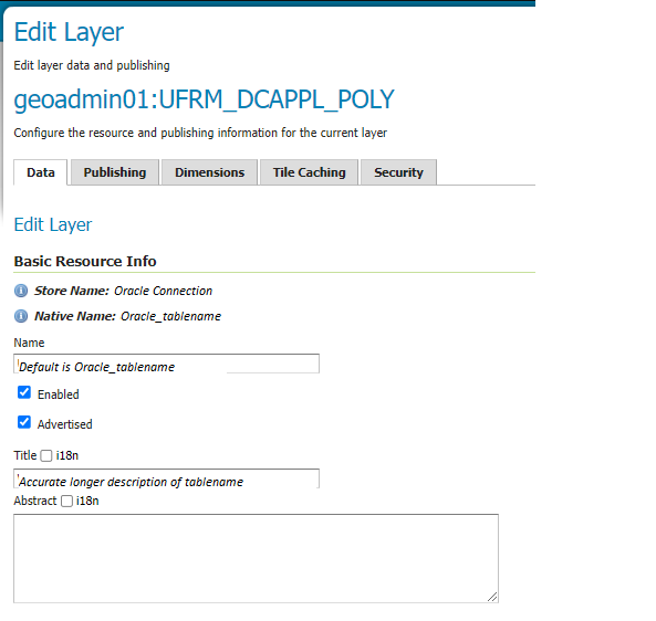
Enabled and Advertised parameters – Layer Config
In GeoServer, the Enabled and Advertised checkboxes play distinct roles in layer configuration:

Enabled:
When a layer is enabled, it means that the layer is available for requests (such as WMS GetMap or WMS GetFeature). If a layer is not enabled, it won’t be accessible for any kind of request. However, it will still appear in the configuration (and in the REST config). Essentially, enabling a layer makes it operational and ready to serve data.
Advertised:
By default, a layer is advertised. An advertised layer is included in the GetCapabilities request and appears in the layer preview. However, if you uncheck the Advertised checkbox, the layer will still be available for data access requests (like WMS), but it won’t appear in any capabilities documents or previews. In other words, non-advertised layers remain functional but are not explicitly listed in service metadata. Remember, enabling a layer makes it operational, while advertising it determines whether it appears in service capabilities and previews

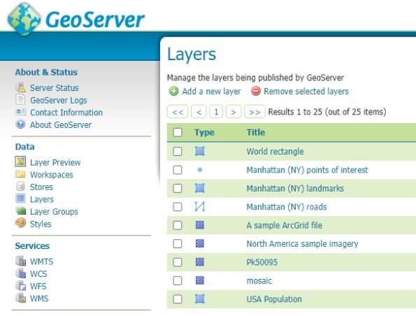
Name and Title parameters – Layer Config
Name:
The Name corresponds to the identifier used to reference the layer in WMS (Web Map Service) requests. It is primarily used for computer interaction and serves as an internal reference default name is usually the name of the table or the name of the referenced view. When creating a new layer for an already-published resource, the Name must be unique to avoid conflicts. Essentially, it’s the technical name associated with the layer.
Title:
The Title provides a human-readable description that briefly identifies the layer to clients. Unlike the Name, which is for computers, the Title is meant for humans to read. It helps users understand the purpose or content of the layer. For example, if you have a layer representing a map of the USA, you might set the Title to “This is a map of USA.” Remember, while the Name is essential for system functionality, the Title enhances user experience by providing meaningful context about the layer1

Security – the Name does not need to be the table or view name you are referencing. This string appears in the URL which may be viewable to the user – you may wish to obfuscate this by changing the name

i18n – Internalization – Layer Config
Internationalization (i18n):
GeoServer supports returning a GetCapabilities document (used for describing available services and layers) in various languages. The i18n functionality is available for the following services:
WMS 1.1 and 1.3
WFS 2.0
WCS 2.0
The i18n editor allows you to provide translations for the title and abstract of various components:
Layers configuration page
Layergroups configuration page
WMS, WFS, and WCS service configuration pages
Additionally, for Styles, there’s a separate i18n configuration (see i18N in SLD).By default, the i18n editor is disabled and can be enabled via the i18n checkbox.

GetCapabilities Document Language:
The language of the GetCapabilities document can be selected using the AcceptLanguages request parameter.GeoServer’s response varies based on the following rules:
Internationalized elements include titles, abstracts, and keywords.If a single language code is specified (e.g., AcceptLanguages=en), GeoServer tries to return content in that language.If multiple language codes are specified (e.g., AcceptLanguages=en,fr), GeoServer attempts to return content in one of the specified languages.

Coordinate Reference Systems – Declared SRS and SRS handling – Layer Config

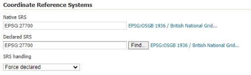
If you are in the UK ensure that Declared SRS is set to 27700

SRS Handling
In GeoServer, the SRS handling setting plays a crucial role in how coordinate reference systems (CRS) are managed. Let’s explore its significance:

Declared SRS:
The Declared SRS specifies the coordinate system that GeoServer publishes to clients. It represents the CRS that clients should use when interacting with the layer. Essentially, it’s the officially declared CRS associated with the layer.
SRS Handling:
The SRS Handling option determines how GeoServer should handle projection transformations when the declared CRS and the native CRS of the data differ. Here are the possible values for SRS Handling:
Force declared (default): In this mode, GeoServer forces the declared SRS upon the data, overwriting the native CRS if necessary.
Other options (not mentioned in the snippet):
Reproject native to declared: GeoServer performs a reprojection from the native CRS to the declared CRS.
Reproject declared to native: GeoServer reprojects from the declared CRS to the native CRS.
None: No reprojection is performed; the data remains in its native CRS.
In summary, the SRS handling setting ensures that data is presented consistently to clients, regardless of the underlying native CRS. It’s a critical aspect of maintaining accurate spatial information in GeoServer1.

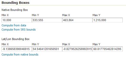
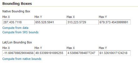
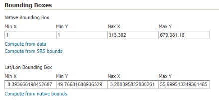
Bounding Box recommendations – Layer Config
Scotland

Min X = 010000
Min Y = 533000

Max X = 464000
Max Y = 1215000

West Lothian

Min X = 287000
Min Y = 655000

Max X = 314000
Max Y = 678000

UK

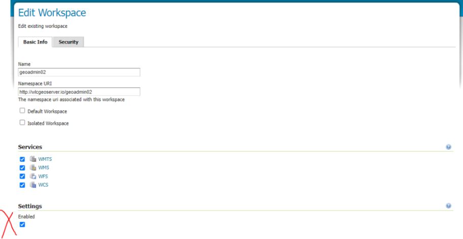
Workspace setup and visibility in WFS
Workspaces can allow for editing and not editing of information although to date I seem to be struggling to isolate layers and workspaces to allow them to be edited or not edited. One thing that is important in our present system is to Enable the settings in the Basic info – without this the layers within the workspace were not showing up in the WFS

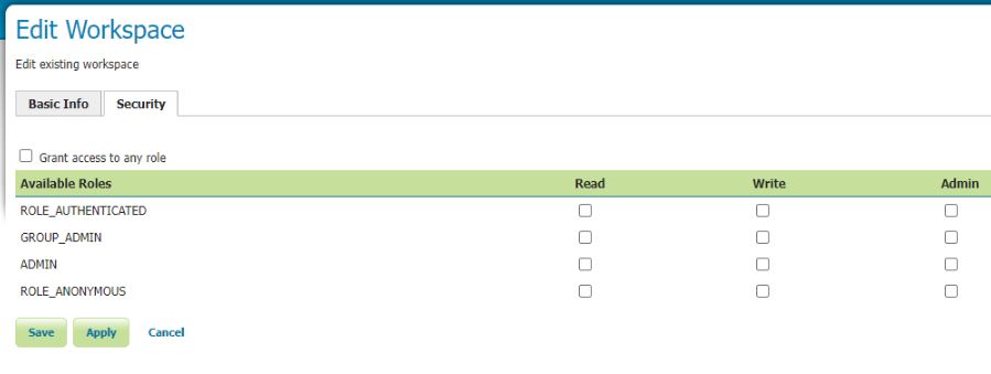
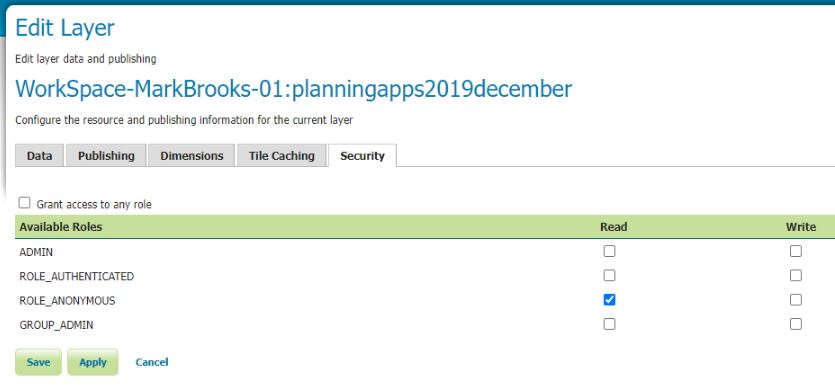
Restrictions on Layers : Important Note

Important – Workspace Security settings override Layer Security Settings

If you need to have different layer security settings within one Workspace you will need to turn off all Workspace security settings e.g see below.

Geoserver Installation (Configuration for SQL Server on Windows)

Once you have your data in an Enterprise Grade database sharing that information becomes important. Some vendors, in particular Digital mapping SAAS vendors want you to transfer your data into their clouds but for a lot of authorities that is categorically impossible for large segments of their data. For example about 3/4 of UK planning authorities run on software built by a company called IDOX Group plc which holds its data in Oracle this cannot be moved. For Geographical data here’s where Geoserver comes in.

Geoserver Official Website

From the website
GeoServer is an open source server for sharing geospatial data.
Designed for interoperability, it publishes data from any major spatial data source using open standards.

GeoServer implements industry standard OGC protocols such as Web Feature Service (WFS), Web Map Service (WMS), and Web Coverage Service (WCS). Additional formats and publication options are available as extensions including Web Processing Service (WPS), and Web Map Tile Service (WMTS).

Another way of putting it Geoserver allows programs that display and manipulate geographic information to display and edit that data while keeping it safe and secure and located in enterprise databases. It can connect to SQL Server / Postgresql and I am told Oracle which are the main relational databases used by Local authorities today so once setup and configured it could be used to compare and contrast information in one location from variable datastores. Datastores that for historical reasons cannot be moved. Here I concentrate on SQL Server because we have a particular issue with new systems needing to connect to SQL Server but it would be great if we could get it working with Oracle as well.

The following are my notes on installation and configuration of Geoserver on Windows linking to SQL Server and in this case a remote(not on the same computer) SQL Azure instance I believe any remote SQL Server instance would be similar. This post is a detailed explanation of the installation of Geoserver locally on a laptop but I believe installation would be exactly the same on a Windows Server machine albeit additional steps would be required to publish to the web either internally or externally.

Its all configuration so remember your host names / IP numbers / ports / usernames / passwords / database, table and column names

To start this tutorial please ensure the following resources are available;

  • SSMS – installation of Sql Server Management Studio
  • SQL Azure instance with privileges to run SQL. Please note you will need to know the port number of your SQL server instance and have a Username and Password for your user.
  • Necessary privileges to set the firewall on the database which you will link to Geoserver –
  • QGIS – installation – If you don’t have a SQL Server instance with geodatabase already that you can use you will probably need this to add at least one record to a geometry enabled table I plan to expand my notes on this but at present you might be able to skip this
  • Geoserver 2.24.1 – installation files
  • Enough privileges on the computer you are installing geoserver to download installation files and move files into a library subdirectory of the c:/program file/geoserver directory
  • WorkFlow Synopsis Overview
    1)Download and install Java runtime engine (as above importantly here I use 11)
    2)Download and install Geoserver (2.24.1 in this case)
    3)Test that the Geoserver Admin dashboard is up and working
    4)Download and configure Geoserver Extension for SQL Server library (SQL Azure example)
    5)Good idea to setup a login specifically to your SQL Azure instance with least privilege – Your SQL Server instance with geodatabases may already have suitable logins. So steps 5 and 6 can be skipped
    6)Good idea to create an example table with Geodatabase in SQL Azure – will be used as a test connection table – NOTE if you already have a SQL Server with geodatabases you could use that instead.
    7)White list IP within the SQL Azure instance firewall rules to Geoserver computer
    8)Opening Geoserver and setting the ‘Store’ to reference your SQL Azure database using the login setup in step 5.
    9)Adding a new layer from the Store made in point 8 and seeing if you can Preview the layer – Ideally you should have a table that has some features in it. Setting the WMS and WFS up in Geoserver with sufficient rights to allow editing (if WFS setup)
    10)I don’t explain it in my post below but the next step would be to test in QGIS to see if you can setup a project in QGIS which can pull from Geoserver against a basemap and you check that the Polygons are actually where you want them to be.

    Workflow Detailed
    1)Download the install Java Runtime via JDK

    There are some complications here
    Initially I tried to use the Java Runtime engine 17 and went through the complete Geoserver installation but on testing I was getting a Java error when trying to view layers. After a short google I came across a stack overflow thread that indicated that geoserver support for JDE 17 was experimental and I should use Java Runtime engine 11. Deinstallation of 17 and installation of 11 solved this.

    Additionally there is the issue of where you obtain the Java Runtime installation from – there is the Adoptium location and then there is Oracle location. Oracle are making moves to charge for use of their Java Runtime engine so it is important that you use Adoptium resource to reduce costs.

    Later I will list the url to the JDK download for Java Runtime engine but it is important to realise that Adoptium is a safe source, well supported and noted as open source.

    https://adoptium.net/en-GB/members/

    so

    Google Search for Adoptium
    https://adoptium.net/en-GB/

    Navigate to other platforms and versions and target windows 64 bit JDK and 11 LTS version and download the .msi.

    After a short delay you will be shown the msi which will be in your downloads folder

    Double click on it to install.

    Now the only thing that is tricky here is to setup the java home directory as follows

    Video Installing Adoptium JDK on Windows

    In particular note this section

    2) Download and install Geoserver

    Go to the official Geoserver web page and follow the links to download the windows installer

    Here I use the windows version of Geoserver version 2.41.1 obtained January 2024 from the following url
    Geoserver Official Website

    See download button and then go to Windows Installer

    I chose the left option and then I chose the Windows Installer option

    This will download Geoserver-2.24.1-winsetup.exe to your download directory and you can then start the geoserver installation process

    Next open up the executable and follow the instructions

    Next agree the licence

    Next we reference the java library installed in the previous step – if you have set the java_home variable correctly it should automatically find JRE 11 for you and it will place it within the path reference below. I don’t have a screenshot of the JRE 11 reference here as on my first installation I referenced the Oracle 17 JRE – (note I went back de-installed geoserver installed JRE 11 and then reinstalled geoserver to counter the proprietary Oracle runtime library and importantly to fix the issue that I was facing of geoserver not being compatible with JRE 17

    The rest of the install from here is standard for a windows install

    Next setup the default admin password – defaults are admin / geoserver

    Set up port geoserver runs on – default is 8080

    Next choose the execution type I like to install geoserver as a service

    Confirm your preferences and then trigger install

    Now you should see geoserver on your local machine as a service which you will need to ensure is running to access properly

    3) Test that Geoserver Admin dashboard is up and working at least locally

    If you have used the same settings as me open a browser and navigate to the following url

    https://localhost:8080/geoserver/web

    Login with the username and password which is usually admin / geoserver

    At which point you should see something similar to the following

    4) Download and configure Geoserver Extension for SQL Server

    At install Geoserver comes with the ability to connect to Postgres but NOT SQL Server so we must install/configure plugin extension to enable Geoserver SQL Server connections.

    Here we go back to the geoserver.org website and go to download but this time instead of choosing the windows installer we look to the Extensions section and choose SQL Server

    This should download geoserver-sqlserver extension plugin

    Next copy all files with the jar suffix into the following directory

    C/program files/GeoServer/webapps/geoserver/WEb-Inf/Lib

    Next restart the geoserver and go back to the local host and sign in

    http://localhost:8080/geoserver/web/?0

    We are now very close to linking to SQL Server prior to that we must whitelist our geoserver so that your SQL Server instances will accept connections from your geoserver. Steps 5 and 6 are more about creating a user and ensuring you have a geodatabase with a georeferenced table skip to 7 if you want to read about white listing in SQL Azure or you have an alternative database that you could use with requirements already set up.

    5) Next its a good idea to create a user with least privilege this will be used to set up the link so go to SSMS

    Least privilege User Login Setup SQL Server

    Here allow the amount of access you wish users to have remembering the principles of least privilege

    6) Lets create an example table with geometry that we will be connecting
    When I first tried connecting to SQL Server (SQL Azure in my case) I didn’t have any georeferenced tables so I created one and added a few records. If you have a database already with tables with geometry or geography you might not need to do this step.

    So open SSMS and navigate to your database and use the following TSQL to create a table here I call it t064

    SET ANSI_NULLS ON
    GO
    
    SET QUOTED_IDENTIFIER ON
    GO
    
    CREATE TABLE [dbo].[t064](
    [PKID] [int] IDENTITY(1,1) NOT NULL,
    [geomcol] [geometry] NULL,
    [sitename] [varchar](30) NULL,
    PRIMARY KEY CLUSTERED
    (
    [PKID] ASC
    )WITH (STATISTICS_NORECOMPUTE = OFF, IGNORE_DUP_KEY = OFF, OPTIMIZE_FOR_SEQUENTIAL_KEY = OFF) ON [PRIMARY]
    ) ON [PRIMARY] TEXTIMAGE_ON [PRIMARY]
    GO

    This is a really simple table with three columns and you might want to link to it through QGIS and just create a few records – I would try and use a default projection of 27700 if you are UK based. I might come back with an example table with records..

    If you want to link to this table for testing then you should try and input at least one record here. I added records using QGIS and I hope to come back to this post and update it to be more specific

    7) White List the IP within your SQL Server or SQL Azure instance.
    Setting IP White List in SQL Azure

    8) Opening Geoserver and setting the ‘Store’ to reference your SQL Azure database using the login setup in step 5

    Navigate to the local host url for Geoserver namely

    http://localhost:8080/geoserver/web/?0

    Go to store and then you should see the following page

    Hit the Add New Store green plus button in the top left corner you will be presented with the following screen

    Fill out as many details as you can

    For SQL Azure this is likely to be similar to the following

    Host = namevariable.database.windows.net (normally unique to instance in SQL Azure)
    Port = 1433 (sql azure default)
    Schema = dbo (sql azure default is dbo but your database maybe bespoke)
    User = uservariable (remember least privilege is a good idea)
    Passwd = passwordvariable (should be unique to your database)
    

    Save and Apply and then your new connection should appear in your store

    Here’s an example…. (see top line)

    For the purposes of this tutorial I setup a login with db_owner rights to the database LandRegisterAzure your mileage will vary.

    9) Next we add the layer which references the SQL Server

    Select Layers within the Data section of the menu (usually to the left of the geoserver dashboard) then hit Add a new layer

    You should get the following windows

    From the drop down select the store which references your SQL server. This will reveal all the tables and views in the database and you scroll through them to the table or view you wish to publish and in the column marked Action will be publish you can hit the Publish highlighted text (I’ve done that here already so under Action our table is marked as Publish again and there is a tick in the column titled Published.

    We can now quickly test to see if things look like they are working by going to Layer Preview.

    Look to the left hand side and select Layer Preview

    Scroll down through the list and identify the layer that you have just added. I now select the open layers option

    A new browser tab will open and if you have successfully configured the SQL Server you should be presented with your layer – without any background

    10) I don’t go into it here but next I will try and write up my notes on QGIS and Geoserver setup – On my laptop I managed to set up a WFS to my SQL Azure instance through Geoserver where the layer was added to a project and I was able to edit information in my SQL Azure database through QGIS and were displayed correctly against a basemap in the right place!!

    –/END/–

    Spatial Data Hub Scotland

    Planning in the UK has for a long time suffered from a classic siloing of data by authority resulting in slow and varied analysis of information. Authorities relied on talented motivated individuals with particular interests and skills to develop bespoke solutions that assisted in the development of things like housing land audits , population forecasts , capital planning and local plan development which while often impressive individually struggled to transfer between authorities.

    The continual improvement of digital tools has dramatically improved standardisation of the attributes of particular spatial data sets and database technology originally developed for accounting systems and flight control systems is starting to be applied to the amalgamation and analysis of planning related information. Within the UK different regions are progressing along this path at different rates. Scotland now has a body the Improvement Service who has a specific remit to collect spatial planning data which they do at something call the Spatial Data Hub.

    The Spatial data hub at 08 January 2024 had 59 datasets listed at Scotland coverage level. Including
    Planning application boundaries
    School Catchment Areas
    Housing Land Supply
    Vacant and Derelict Land
    Employment Land

    The improvement service has been building these datasets for a number of years now however last year they expanded general access to much of the information and I have since been experimenting with it to see what can be achieved.

    SQL Server Express – Connection to QGIS issues with geometry display

    I was having issues displaying polygons stored in SQL Server Express locally within a QGIS 3.28 project.

    After having quizzed unsuccessfully GPT 4.0 I found the answer on good old Stack Overflow.

    As part of your SQL Server Express installation you should have installed SQL Server Configuration Manager. Open this administration package and navigate to your instance to show the following;

    Make sure both Named Pipes and TCP/IP are enabled.

    That fixed it for me
    Important note the host connection string IS case sensitive and sometimes when you use the properties from within SSMS to look at the hostname it capitalise things so watch out! That caught me out for half an hour!!

    And here is my definition of the geometry table

    CREATE TABLE [dbo].[geometry_columns](
    [pkid] [int] IDENTITY(1,1) NOT NULL,
    [f_table_catalog] [varchar](50) NULL,
    [f_table_schema] [varchar](50) NULL,
    [f_table_name] [varchar](100) NULL,
    [f_geometry_column] [varchar](50) NULL,
    [coord_dimension] [int] NULL,
    [srid] [int] NULL,
    [geometry_type] [varchar](50) NULL,
    PRIMARY KEY CLUSTERED
    (
    [pkid] ASC
    )WITH (PAD_INDEX = OFF, STATISTICS_NORECOMPUTE = OFF, IGNORE_DUP_KEY = OFF, ALLOW_ROW_LOCKS = ON, ALLOW_PAGE_LOCKS = ON, OPTIMIZE_FOR_SEQUENTIAL_KEY = OFF) ON [PRIMARY]
    ) ON [PRIMARY]
    GO

    Add POSTGIS extension to Azure Postgres Database – Worked Example

    Firstly we need to allow for the extension on the server.
    Within the Azure portal navigate to server parameters

    Search for azure.extensions

    Select which extensions to add
    REMEMBER to save before exit!

    Wait a short period while the extension is loaded onto the server..

    Some points
    Azure Database for PostgreSQL supports a subset of key PostgreSQL extensions as listed HERE. This information is also available by running SHOW azure.extensions;. Extensions not listed in this document aren’t supported on Azure Database for PostgreSQL – Flexible Server. You can’t create or load your own extension in Azure Database for PostgreSQL.

    After extensions are allow-listed and loaded, these must be installed in your database before you can use them. To install a particular extension, you should run the CREATE EXTENSION command. This command loads the packaged objects into your database.

    The extension(s) should now be listed against your database.

    Postgres – Export a Spatial database and then Importing again (pg_dump + psql utilities)

    Lets take this from the beginning. The first thing you need to do is be on the physical machine where the database is running.

    Next check that the database server is up and running

    To do that

    Go to the windows bar click on the search icon and type in

    Services

    Scroll down to P and look for the name postgresql this and look to the Status column in the above example there are two postgres 11 and postgres 14 of the two only 14 shows as Running.

    There are several Utility executables that come with every postgres installation.

    The standard installation set up puts these into a directory equivalent to the following;

    We need to navigate at the command prompt to the location of the executable we are interested in. Technically you could qualify the path to, the executable when running a command, but I tend to navigate to the location.

    So firstly in the search button go to the command prompt

    cmd

    cd C:\Program Files\PostgreSQL\14\bin

    pg_dump -U postgres -W -F p -d dbspatialhub > c:\sql\dbspatialhub.sql

    pg_dump -U postgres -W -F p -d dbspatialhub > c:\sql\dbspatialhub.sql

    and here is a string that works if your database is on the local server with a non standard port / substitute 5433 for your port

    pg_dump -U postgres -h localhost -p 5433 -d dbsource > c:\sql\dbsourceexport.sql

    run this command – you will note that I qualify the output directory here. I prefer to do this as I don’t particularly like writing and deleting files into the program directory. I prefer this directory to be reserved for standard files and reduce the likelihood of me in anyway accidentally deleting an important file.

    You should be presented with the Password: option you will need to input the password for specified User (-U) complete

    Success will be shown as a return to the former prompt with no message.

    and running a DIR on the directory look for the sql file…

    Next from either psql prompt or from within PGAdmin4 create a database you are going to import the sql into and ensure that the postgis extension is installed. Remember this is the psql prompt and not DOS command line prompt.

    CREATE DATABASE dbspatialhubnew
    CREATE EXTENSION postgis
    

    Now you have to go back to the command prompt (and the correct directory).

    If you are on a different port add the following string -p 5434

    psql -U postgres -d dbspatialhubnew -f c:\sql\dbspatialhub.sql

    After being asked for the password the import will start and continue showing a list of various commands and data being executed and imported.
    Similar to below.

    Now you can go back to a client such as QGIS , link to the database to start confirming a successful import.

    Congratulations you have copied a database.

    It should be noted that as it stands I am having problems importing the layers table which has the format of the boundaries for tables.
    I will continue to work on this.

    QGIS – Working with Free BASEMAP Services for Desktop Projects (Bing and Google Maps Aerial and Lines)

    As soon as you need to practically implement any information in Spatial Databases display of the information through a mapping front end becomes absolutely vital. Many database administrators are used to simply going into their favourite database editors and displaying the raw subsets of tables and queries. That works well for financial transactions and inventory tables were collapsing the attributes of objects into single digits is often valuable or possibly preferable to simple photos. When dealing with boundary information the complete opposite applies. Display of information as simple screens of matrix numbers is completely useless.

    Additionally often boundaries make zero sense unless referenced to the land beneath them either through aerial photography or topographic maps.

    In a previous time where I worked we actually commissioned a company to give us aerial photos of a local authority. This was not an insignificant amount of money and was probably only marginally reduced by the vendor having multiple channels of sale. Google and Microsoft are now very good in offering very good aerial and line interpretations for limited use to companies and individuals. This is absolutely great as it can be used as background either to confirm accuracy of other information or as data upon which to calculate further information (eg routing).

    So how can an individual get up and started with some of these basemaps.

    Sometime recently (I know not when exactly) QGIS changed its implementation of Open Street Maps through their desktop – rather than being an additional plugin Open Street Map provision is now included on install.

    Here I am working with QGIS version 3.10

    Now you should be presented with the Data Source Manager Dialog which looks like this

    Now expand the XYZ Tiles

    You can then double click on any one of the three and the WMS will be transferred into the layer panel

    Layer > Data Source Manager > XYZ

    Thank you to Google and Microsoft and OSM and QGIS for a great implementation.

    IDOX – Using Public Access to find Planning Application History

    A significant number of authorities in the UK have the same software that allows members of the public viewing access to most of their recent planning application data. The last time I looked the software was in place for almost the whole of Scotland, Northern Ireland and close to 3/4 of authorities in England and Wales.

    Part of this provision includes a public access web site that allows members of the public access to planning application details via a mapping screen. With practice this can be used to search and research planning application history. When first using the public website users tend to be defeated by the user interface.

    Here’s a quick guide to assist in finding available planning applications relative to a particular site if you know its location on a map.

    We will take West Lothian as an example. The UI slightly varies between councils but the principles are the same for a significant number of authorities

    Firstly navigate to the Public Access Search screen of the authority that you are interested in.

    https://planning.westlothian.gov.uk/publicaccess/

    You should be presented with the following screen.

    Two thirds of the way down on the right is a tab marked – Map – click this.

    You should see something similar :-

    Using your mouse navigate to the land parcel you are interested in determining the planning application history for.

    Next hit the filter ICON

    Note on some authority sites this has been replaced by a drop down combination on the right.

    Hitting this icon on West Lothian site reveals a slider – initially it is set to 6 months for West Lothian

    Chances are you will want to know all of the planning application history so move that slider all the way across to all time.

    Now back on the map you should see many more boundaries representing many more planning applications.

    Users can now zoom in on the particular site they are interested in e.g. Wilkieston below

    Now using the mouse you can click at the position you are interested in and the attributes of the planning application at the location you click will be revealed in a further dialog.

    At this point you can note down the planning application references for further research or you can hit the link marked Application Details – here I click on the link related to 0761/P/18

    Which takes you to the Planning Application details page.

    Want to see any available associated documents linked to the application.

    Look to the text line beneath the table of attributes. The 2 documents is a link that takes you to available docs linked to the application. The number will be different according to the planning application.

    Clicking on it brings up the Planning Application Documents screen where you should be able to download or view the documents.

    Postgres Command Line : psql : Create a switch to determine whether an Arc has a clockwise or anti-clockwise direction

    This is a post focused around Network distance measurement using POSTGIS and routing plugins.. This discusses the use of Ordnance survey Road Network information and its preparation in using it for routing.

    The Ordnance Survey open source road network layer includes roundabouts that have an attribute value of roundabout. Great but looking at them closely some of the constituent arcs are digitised in a clockwise direction while others are digitised in an anti-clockwise direction. When using dijkstra routing with weighting to prevent incorrect pathing it is necessary to ensure that networks are weighted in the correct fashion. Directional weighting only works if you know the direction and you weight appropriately. For use with directional routing in the UK roundabouts any directional weighting should prevent travel in anticlockwise direction. ST_reverse will correct incorrect direction BUT the Ordnance survey layer seems to have no attribute that consistently indicates whether an arc on a roundabout has or has not been digitised correctly. Marking lines with direction and viewing them we see the random nature of many arcs on roundabouts.

    Here is Sheriff Hall Roundabout on Edinburgh City Bypass

    Here is Straiton roundabout just north of the bypass

    and finally Hermiston Gate roundabout again following the theme on Edinburgh city bypass

    It got me thinking was there a way to determine whether arcs on roundabouts could be determined to be clockwise or anti-clockwise?

    Having thought about it in my head quite a bit I determined that it probably would be possible if we knew three points and could create some kind of virtual graph with the start point being at 6 and a finish at 12 with mid points at 9 if travelling in a clockwise position and 3 if travelling in an anti-clockwise position.

    I had a look around and the following post seemed to tally with the idea of three points and positive and negative relating to clockwise or anticlockwise.

    Maths to determine direction of an arc

    Having looked at this I set about working through the problem in Excel to see if I could get consistent results.

    Firstly I created a set of directions North West South and East and placed some coordinates that could be used in calculations.

    I then went forward and tested whether I could identify the direction of various arcs from these coordinates in excel using the formula identified on Stack Exchange.

    Here I replaced a,b,c with b Beginning, m Middle and f Finish

    And I decided to work through manually in excel to ensure that I had the linear algebra correct.

    and further testing figures

    So firstly I create a separate table that just shows the roundabouts

    CREATE TABLE t001roundaboutsntroadlink as select id pkidt001, st_linemerge(geom) as geom from ntroadlink where formofway = 'Roundabout';

    In the above I use st_linemerge to ensure that all geometry is linestring as this is necessary to use the st_startpoint and st_endpoint postgis functions.

    Next I added the the required variables from stack overflow algebra to the line table

    ALTER TABLE t001roundaboutsntroadlink add column bx float(8),
    Add column by float(8),
    Add column mx float(8),
    Add column my float(8),
    Add column fx float(8),
    Add column fy float(8),
    Add column ux float(8),
    Add column uy float(8),
    Add column vx float(8),
    Add column vy float(8),
    Add column uxtimesvy float(8),
    Add column uytimesvx float(8),
    Add column uxv float(8);

    Next I needed to identify a b beginning, m middle and f finish point for each line that I wanted to test.

    b points (beginning)

    CREATE TABLE t002bpoints AS SELECT pkidt001 as pkidt001,st_startpoint(geom) as geom, st_x(st_startpoint(geom)) as bx, st_y(st_startpoint(geom)) as by from t001roundaboutsntroadlink;

    m points (middle)

    CREATE TABLE t002mpoints AS SELECT pkidt001 as pkidt001,st_lineinterpolatepoint(geom,0.5) as geom, st_x(st_lineinterpolatepoint(geom,0.5)) as mx, st_y(st_lineinterpolatepoint(geom,0.5)) as my from t001roundaboutsntroadlink;

    f points (finish)

    CREATE TABLE t002fpoints AS SELECT pkidt001 as pkidt001,st_endpoint(geom) as geom, st_x(st_endpoint(geom)) as fx, st_y(st_endpoint(geom)) as fy from t001roundaboutsntroadlink;

    It was then a case of simple update queries to complete the table

    update t001roundaboutsntroadlink set bx = st_x(st_startpoint(geom));
    update t001roundaboutsntroadlink set by = st_y(st_startpoint(geom));
    update t001roundaboutsntroadlink set mx = st_x(st_lineinterpolatepoint(geom,0.5));
    update t001roundaboutsntroadlink set my = st_y(st_lineinterpolatepoint(geom,0.5));
    update t001roundaboutsntroadlink set fx = st_x(st_endpoint(geom));
    update t001roundaboutsntroadlink set fy = st_y(st_endpoint(geom));
    update t001roundaboutsntroadlink set ux=mx-bx;
    update t001roundaboutsntroadlink set uy=my-by;
    update t001roundaboutsntroadlink set vx=fx-mx;
    update t001roundaboutsntroadlink set vy=fy-my;
    update t001roundaboutsntroadlink set uxtimesvy = ux*vy;
    update t001roundaboutsntroadlink set uytimesvx= uy*vx;
    update t001roundaboutsntroadlink set uxv = uxtimesvy-uytimesvx;

    Labelling up the roundabouts Hermiston Gate now looks like

    And Sheriff Hall Roundabout now looks like this

    Compared with a correctly directed roundabout

    CREATE TABLE t001roundaboutsntroadlinkcorrected AS TABLE t001roundaboutsntroadlink;

    And now correct the items display as previous and see what we see.

    UPDATE t001roundaboutsntroadlinkcorrected set geom = st_reverse(geom) where uxv > 0;

    Sheriff hall roundabout now

    and some proof that reasonable number of lines were updated.

    Which is an indication that all roundabouts arcs have been corrected properly

    But a zero uxv value indicates a straight line.

    It should however be possible to match starts with finishes for overlying points and where a line has 0 value of uxv and its ends and finishes are not matched with adjacent opposites create a switch to reverse the direction of all lines that are incorrect compared to their neighbours thus only correcting incorrect directions. Haven’t done that in this case.

    021 Postgres with PostGIS plugin – Create junction table sites in catchments

    This is a working example of how it would be possible to set up code that would automatically allocate for example housing sites to School Catchment areas. It could also be used to list constraints relevant to particular housing sites. This is more complicated in that it will indicate what percentage of the housing site is within which catchment areas and therefore allows for a single housing site being in multiple catchment areas. I am planning on coming back and expanding on this post. In this respect it represents a refinement of this Post

    So we need two tables

    t001asites which has a geometry field called geom
    and another table which will be the catchments table called
    t002bcatchments which has a geometry field called geom.

    Both tables must have a serial primary key of pkid and both tables must be polygon data and the geom field MUST be defined as polygon and NOT multipolygon.

    Air code is as follows.

      1. Create table containing digitised polygons of housing sites.
      2. Create table containing digitised polygons of catchments.
      3. Measure the area of the housing sites and place that value in an area column within the housing sites table t001asites.
      4. Split the housing sites by the catchment boundaries ensuing that each split polygon inherits the catchment it was split by.
      5. Re-measure the areas of these split sites and add an area column to store the new calculations.
      6. Divide figure obtained in 5. by figure obtained in 3 which will indicate the proportion of the housing site is in which catchment.
      7. Perform a least remainder method on the individual sites grouped by their original housing sites to ensure the proportions sum to 1.

    So to the code

    BEGIN;
    SET LOCAL check_function_bodies TO FALSE;
    CREATE OR REPLACE FUNCTION part01catchjunctionmaker() returns void as $$
    Alter table t001asites add column area integer;
    $$ LANGUAGE SQL;
    CREATE OR REPLACE FUNCTION part02catchjunctionmaker() returns void as $$
    Update t001asites set area=ST_Area(geom);
    $$ LANGUAGE SQL;
    CREATE OR REPLACE FUNCTION part022catchjunctionmaker() RETURNS void AS $$
    DROP TABLE IF EXISTS t200;
    $$ LANGUAGE SQL;
    CREATE OR REPLACE FUNCTION part03catchjunctionmaker() RETURNS void AS $$
    CREATE TABLE t200 AS select a.pkid as t001pkid, b.pkid as t002pkid, a.area as t001area, ST_intersection(a.geom, b.geom) as geom FROM t001asites a, t002bcatchments b;
    $$ LANGUAGE SQL;
    CREATE OR REPLACE FUNCTION part04catchjunctionmaker() RETURNS void AS $$
    ALTER TABLE t200 add column pkid serial primary key, add column area integer,add column proportion decimal (10,9);
    $$ LANGUAGE SQL;
    CREATE OR REPLACE FUNCTION part06catchjunctionmaker() RETURNS void AS $$
    UPDATE t200 SET area=ST_Area(geom);
    $$ LANGUAGE SQL;
    CREATE OR REPLACE FUNCTION part07catchjunctionmaker() RETURNS void AS $$
    DELETE from t200 where area=0 or null;
    $$ LANGUAGE SQL;
    CREATE OR REPLACE FUNCTION part08catchjunctionmaker() RETURNS void AS $$
    UPDATE t200 SET proportion= cast(area as decimal)/cast(t001area as decimal) WHERE area > 0;
    $$ LANGUAGE SQL;
    CREATE OR REPLACE FUNCTION part088catchjunctionmaker() RETURNS void AS $$
    DROP table IF EXISTS t201;
    $$ LANGUAGE SQL;
    CREATE OR REPLACE FUNCTION part09catchjunctionmaker() RETURNS void AS $$
    Create table t201 as Select pkid,t001pkid,t002pkid, t001area, area, proportion, sum(proportion) OVER (PARTITION BY t001pkid ORDER BY t001pkid, proportion) as cum_proportion FROM t200 ORDER BY t001pkid, proportion;
    $$ LANGUAGE SQL;
    CREATE OR REPLACE FUNCTION part10catchjunctionmaker() RETURNS void AS $$
    Alter table t201 add column value decimal (14,9),
    Add column valuerounded integer,
    Add column cumulvaluerounded integer,
    Add column prevbaseline integer,
    Add column roundproportion integer;
    $$ LANGUAGE SQL;
    CREATE OR REPLACE FUNCTION part11catchjunctionmaker() RETURNS void AS $$
    UPDATE t201 set value = proportion * 100;
    $$ LANGUAGE SQL;
    CREATE OR REPLACE FUNCTION part12catchjunctionmaker() RETURNS void AS $$
    UPDATE t201 set valuerounded = round(value,0);
    $$ LANGUAGE SQL;
    CREATE OR REPLACE FUNCTION part13catchjunctionmaker() RETURNS void AS $$
    update t201 set cumulvaluerounded = round((cum_proportion*100),0);
    $$ LANGUAGE SQL;
    CREATE OR REPLACE FUNCTION part14catchjunctionmaker() RETURNS void AS $$
    update t201 set cumulvaluerounded=100 where cumulvaluerounded = 101;
    $$ LANGUAGE SQL;
    CREATE OR REPLACE FUNCTION part15catchjunctionmaker() RETURNS void AS $$
    update t201 set prevbaseline = round((cum_proportion - proportion)*100);
    $$ LANGUAGE SQL;
    CREATE OR REPLACE FUNCTION part16catchjunctionmaker() RETURNS void AS $$
    update t201 set roundproportion = (cumulvaluerounded-prevbaseline);
    $$ LANGUAGE SQL;
    CREATE OR REPLACE FUNCTION part17catchjunctionmaker() RETURNS void AS $$
    DELETE from t201 where roundproportion=0 or null;
    $$ LANGUAGE SQL;
    CREATE OR REPLACE FUNCTION part18catchjunctionmaker() RETURNS void AS $$
    alter table t201 add column proppercent decimal(3,2);
    $$ LANGUAGE SQL;
    CREATE OR REPLACE FUNCTION part19catchjunctionmaker() RETURNS void AS $$
    update t201 set proppercent = cast(roundproportion as decimal)/100;
    $$ LANGUAGE SQL;
    COMMIT;
    

    and now a function to pull it all together;

    CREATE OR REPLACE FUNCTION createcjt()
    RETURNS TEXT AS
    $BODY$
    BEGIN
    PERFORM part01catchjunctionmaker();
    PERFORM part02catchjunctionmaker();
    PERFORM part022catchjunctionmaker();
    PERFORM part03catchjunctionmaker();
    PERFORM part04catchjunctionmaker();
    PERFORM part06catchjunctionmaker();
    PERFORM part07catchjunctionmaker();
    PERFORM part08catchjunctionmaker();
    PERFORM part088catchjunctionmaker();
    PERFORM part09catchjunctionmaker();
    PERFORM part10catchjunctionmaker();
    PERFORM part11catchjunctionmaker();
    PERFORM part12catchjunctionmaker();
    PERFORM part13catchjunctionmaker();
    PERFORM part14catchjunctionmaker();
    PERFORM part15catchjunctionmaker();
    PERFORM part16catchjunctionmaker();
    PERFORM part17catchjunctionmaker();
    PERFORM part18catchjunctionmaker();
    PERFORM part19catchjunctionmaker();
    RETURN 'process end';
    END;
    $BODY$
    LANGUAGE plpgsql;
    

    019 Postgres and Postgis: Load multiple shape files into a Postgis database

    Environment
    Windows 10
    Postgresql 11

    To start you need a set of shape files that you know the location of.

    For demonstration purposes I use the OS Open Road open data shape files.

    Link to OS Open Data

    Next within explorer I create a directory in the c:\ root called data.
    And then I create two subdirectories.
    1 – shp
    2 – sql

    Place all the shape files you wish to be loaded into a postgis database into the newly created c:\data\shp directory.

    Next we will make sql text files that can be used to transfer the information from shape format into Postgis. At this point it is not necessary to even know what database you are going to place the shape files into.

    Next open up the command prompt and navigate to the bin directory of your particular postgres installation. Standard as follows :-

    Next I copy in the below text.

    For %f in (C:\data\shp\*shp) do Shp2pgsql –s 27700 %f public.%~nf > C:\data\sql\%~nf.sql

    This will take all the shape files in the C:\data\shp\ directory and create sql text files placing them in the C:\data\sql\. After completion you may wish to go to the directory and check that creation has occurred. You can even look at the text within a single file preferably with some kind of code editor to check that it looks approximately correct.

    Next within psql I create the target database and apply the postgis extension.
    create database osopenroaddb;
    create extension postgis;

    Next, unless you have a lot of time on your hands you will want to go to the
    C:\Users\Mark\AppData\Roaming\postgresql
    and open up the pgpass.conf file and place the following line in it.

    localhost:5432:*:postgres:yoursecretpassword

    Without that line you will be asked for a password everytime a new sql file is run.

    Next back in command prompt bin directory do the following. Note no password it takes it from the pgpass.conf file.

    For %f in (c:\data\sql\*sql) do psql –h localhost –d osopenroaddb –U postgres –f %f > nul

    If you have a lot of big files this could take a while to run. But once finished all your shape files should now be in your postgis instance in the specified database.

    018 Postgres : Export Data and Structure of a Single database from a Postgres instance / Import Data and Structure of a Single database into a Postgres Instance

    Demonstration environment and programs
    Windows 10
    Postgres Version : 11.2
    QGIS desktop version : 3.4.4

    My working through of a process to export a single database (structure and data) from a Postgres Instance, the database has PostGIS and pgrouting extensions enabled, followed by importing into in this example the same instance but in principle could be a different instance.
    Access the command prompt (RUN AS ADMINISTRATOR)

    PLEASE NOTE run the command prompt as administrator or you will get frequently get an ACCESS DENIED message after using pg dump command.

    Navigate to the directory of the PostgresVersion from which you wish to export the database. This will typically be the bin subdirectory of the version of your postgres ( here 11 ). You can ensure that pg_dump.exe is here if you do a dir on the directory to reveal alternatively you could reference the full path to pgdump and then pass the parameters to it subsequently.

    eg

    Next place in the parameters of the database what database you wish to export along with the name that you want to call the exported file and then hit return.

    pg_dump -U postgres -p 5432 edinburghrouting > c:\dbexport.pgsql

    Hitting return depending on the security of your instance you will be prompted for a password.

    Enter the password hit return

    When I do this on my home computer there is no return message but going into the C drive I can see that dbexport.pgsql now exists.

    Next we want to create a blank database this is required to import the data and structure into.
    This we do in psql signed in as a user with sufficient privelege.

    Now back in the command line running as administrator we can run the following.

    psql -U postgres importededinburghrouting < c:\dbexport.pgsql

    Pressing return depending on your security you should be asked for your password.

    Once this is done it goes through a process of recreating the structure of the database then importing all the data

    For me the first lines look like this

    and the last look like this

    Now looking at the instance as a whole we can see the imported database

    and here I am displaying geographical information through QGIS to get an idea of the data and ensure that it appears to be all correct.

      SUMMARY


    There are quite a lot of tutorials online on how to do this but most seem to skip over some details - I've tried to be as accurate as possible but depending on you setup there may be differences. Nonetheless this is an extremely important task to perform so worth practicing to get right.

    QGIS and PostGIS : Identifying direction of a vector

    If using the dijkstra function with direction turned on it is important to identify the order in which the nodes of a vector line have been digitised. This is called the direction, dijkstra can use this with a reverse_cost attribute to handicap wrong movement along lines to such an extent that the correct path can be calculated around things like roundabouts.

    Here is an example of the roundabout in Straiton in Edinburgh just North of the A720 bypass. While some of the lines have a correct anti clockwise orienation clearly some have been incorrectly digitised.

    First we can see this by displaying the network in QGIS but using the styling to arrow the direction.

    The function that can be used to reverse such inaccuracies if you can’t resort to buying a correct dataset try ST_REVERSE

    016 Postgres command line : psql : Strip out the Z coordinate from a geometry field

    When creating a topology the geometry field cannot contain a Z coordinate.

    OK but the Ordnance Survey Open Data highways layers containse a Z coordinate. Previously I had stripped this out using the latest version of QGIS which has a tick box in the front end that allows for import stripping of the z coordinate in the process. If you don’t have access to the latest QGIS version how can you strip out the z coordinates.

    ST_FORCE2D

    ALTER TABLE public.nuroadlink ADD COLUMN geom2(multilinestring,27700);
    UPDATE public.nuroadlink SET geom2 = ST_FORCE2D(public.nuroadlink.geom);
    ALTER TABLE public.nuroadlink drop column geom;
    ALTER TABLE public.nuroadlink RENAME COLUMN geom2 TO geom;

    013 Postgres command line : psql : Using ST_Within function to build junction tables to compare 2 separate polygon tables

    First off let us create a new database to hold our examples in.

    CREATE DATABASE stwithindb;
    

    Now add the postgis extension.

    Lets create two tables one called fields and one called plots

    CREATE TABLE
    t00001fields
    (
    pkid serial primary key,
    fieldname varchar(50),
    geom geometry(polygon,27700)
    )
    ;
    CREATE TABLE
    t00002Plots
    (
    pkid serial primary key,
    plotname varchar(50),
    geom geometry(polygon,27700)
    )
    ;

    Now lets go to QGIS connect to the PostGIS instance add the tables and create some test data manually.

    Here I have added fields in green with bold number labels and plots in brown with smaller number labelling. The numbers represent the pkid fields.

    Now here I can quickly run a query to identify the plots that are in fields

    SELECT t00002plots.pkid
    FROM
    t00002plots,
    t00001fields
    WHERE 
    ST_WITHIN(PUBLIC.T00002PLOTS.GEOM, PUBLIC.T00001FIELDS.GEOM);

    And it correctly identifies that plot 1 is within the fields layer.

    But what would be great in an application is to have some kind of junction table that individual master records could display their children on. For this we need a junction table that links between the field and plots table showing the pkids from each.

    SELECT t00002plots.pkid as Plotspkid,t00001fields.pkid as Fieldspkid
    FROM
    t00002plots,
    t00001fields
    WHERE 
    ST_WITHIN(PUBLIC.T00002PLOTS.GEOM, PUBLIC.T00001FIELDS.GEOM);

    Now I will move plot 2 into field 3 and rerun the above.

    The layer now looks like

    and running the former query we get.

    Now its possible to either create a junction table to hold this information..

    eg

    CREATE TABLE t00010fieldplotjunction AS 
    SELECT t00002plots.pkid as Plotspkid,t00001fields.pkid as Fieldspkid
    FROM
    t00002plots,
    t00001fields
    WHERE 
    ST_WITHIN(PUBLIC.T00002PLOTS.GEOM, PUBLIC.T00001FIELDS.GEOM);

    or we can create a view that will constantly calculate this everytime it is seen

    CREATE VIEW v001FieldPlotJunction AS
    SELECT t00002plots.pkid as Plotspkid,t00001fields.pkid as Fieldspkid
    FROM
    t00002plots,
    t00001fields
    WHERE 
    ST_WITHIN(PUBLIC.T00002PLOTS.GEOM, PUBLIC.T00001FIELDS.GEOM);

    Now if I add a few more plots and fields and then pull up the view we shall see that everything has been adjusted

    and running the view we now get

    In some circumstances this calculation may be expensive so we may wish to run and create a junction table overnight other times we may be happy to do it fully dynamically. Of course in a front end you could query and filter such that only one record was compared against the fields plot at anytime. Very useful nonetheless.

    011 : Postgres amalgamate consecutive lines into a single line in a table

    Here we take much of the work covered in post 010 and take the parts and user st_union to merge into a single record and place it in a table created by transforming a view into a table

    Firstly go to your psql line and ensure that you are logged in with a username that you wish to be the owner of the table. In my case general

    logging into edinburgh routing database

    Now same measurement as before but this time we shall make a view out of the measurements then load that into a new table before deleting the view leaving us with the table with a combined measurement.

    CREATE VIEW v001firstmeasurement AS SELECT seq,  id1 AS node, id2 AS edge, cost, geom, agg
      FROM pgr_dijkstra( 'SELECT id, source, target, st_length(geom) as cost FROM public.t01roadnetwork', 15883, 10967, false, false  ) as di
      JOIN public.t01roadnetwork pt ON di.id2 = pt.id ;
    
    CREATE TABLE t003 as select sum(cost), st_union(geom) from v001firstmeasurement;
    
    DROP VIEW v001firstmeasurement;

    It is important in notepad to remove the blank spaces in the editor this looks as follows.

    We then should then get some kind of confirmation that the view and table are created before the view is then dropped again. There might be a more efficient way of doing this but this was my first experiment. And we can go back to QGIS 3.4 and display the now single line in our project. Complete with now accurate measurement. It should be noted that if you were wanting to do multiple line measurements you would need to step out of the create statement and use an insert statement for all subsequent insertions as follows.
    insert into t003(sum,st_union) select sum(cost),st_union(geom) from v001firstmeasurement;
    
    This would allow you to do multiple measurments. I haven’t added up the measurement but it looks about right.

    004 Postgres Command Line : psql : Create a spatially enabled table

    For this you will need to have a version of Postgres Database engine installed and running and you will need to have created a database which has the PostGis extension installed.

    Open psql
    Login to the database you wish to create the table in

    type the following

    CREATE TABLE t001landparcels (PKID SERIAL PRIMARY KEY, PARCELNAME VARCHAR(50), GEOM GEOMETRY(POLYGON,27700));

    Here I do this and then check on the tables with the \dt command before inspecting the columns itself using the \d command.

    and here I open up QGIS and link to my local postgres instance and the exampledb database;

    and here I connect to it and draw a polygon. If you are wondering where it is this is InchKeith in the Firth of Forth and island very visible from George Street in Edinburgh. If you have flown into Edinburgh you will have flown almost over it.

    and here after having digitised a single polygon I look at the contents of the table

    SELECT count(*) FROM t001landparcels;

    Produces the more helpful count of records in the table.

    002 Postgres Command Line : psql : Enabling extensions (PostGIS) to a database

    So you have an existing database in PostGres that you wish to add the PostGIS extension to.

    You will need to be logged in with a username that has superuser privileges.
    Here let me do this using the postgres default account that on my instance has superuser access.

    Here rather than logging in at the start I am choosing to change the connection to a different database

    This is done by using

    \c DatabaseName;

    or

    \connect DatabaseName;

    Please note that the semicolon is vital in performing the instruction.

    The way I have discovered to do this is by opening the database and then allocating the postgis extension to the database once it is open.

    Let us first examine the tables in our blank database before the extension is enabled.

    \dt

    Now let us enable the extension.

    CREATE EXTENSION postgis;

    Let us now examine the database tables

    \dt

    Enabling the PostGIS extension adds this table along with the ability to add geometry types of varaibles within tables.

    MS Access Front End – Linked to PostGreSQL back end – a simple walk through using Access 2003

    As I have indicated before MS Access makes a brilliant ETL tool. Important in this is being able to connect to different databases. I have set out how to connect to MySQL and SQLAzure before – the following sets out how to connect to PostGres.

    To follow along you will either need PostGres installed on your local computer or alternatively all required connection parameters to a database in the cloud or on your lan.
    PostGres Download

    You will also need to Download and install a PostGreSQL ODBC driver – these are available at the following(March 2018).

    PostGres ODBC Drivers

    Scroll down the list – here I went to the bottom and obtained x64 version – MSI are downloaded (Microsoft Windows Installer files) – Install and then move to the next step.

    Next create a blank database and right click in the white area to reveal a menu – select link tables.

    You should now be presented with the Select Data Source dialog. Here I hit New…

    This brings up the Create New Data Source dialog which lists database drivers scroll down through the list to PostgreSQL Unicode and select

    Give your DSN an appropriate name and then go back to link table but this time rather than hitting the new button navigate to where you saved your DSN and select it and press OK.

    The ever important parameters – you just need to know these – if you set up PostGres and you can get in through PG Admin selecting properties on the database should reveal the panel that will give you some guidelines. You may wish to double click on the image below so you can get a closer link of how I place my parameters in. I have opened the PGAdmin dialog here and placed it alongside the MS Access database window to show the properties I am transferring across.

    Hitting OK should present you with the tables in your database.

    And here is a demonstration with the link in place along with the table open and a simple form shown.

    Add Open Street Map to Background QGIS Project and then Digitise against imported Raster

    The following is a workflow that can be used to get a raster base map of anything into QGIS which you then reference to Open Street Map Layers ready for digitising against. This will be useful for approximate digitising of masterplans and approximate digitisation of housing completions.

    Firstly ensure you have dowloaded QGIS and added the following two plugins
    OpenLayers Plugin

    Georeferencer GDAL
    Plugin

    Opening QGIS now lets add the the Open Street Map Raster

    From a blank project selection of Open Street Map should give you the following result

    Now zoom to the approximate location where you wish to have a unique basemap. You will be referencing points on this map to points on your imported raster so you should zoom into a location to the extent that you can identify common locations between the two maps.

    Identify the basemap you wish to have in your particular QGIS map here I choose freely available masterplan from Calderwood development in West Lothian from planning application 0524/P/09

    Within the menus navigate to
    Raster / Georeferencer /

    You should be presented with the following window.

    Hit the add raster button in the top left

    Select the basemap you wish to add to your project and ensure that the coordinate system that you choose is OSGB 1936 / British National Grid

    Next you want to add reference points to the basemap that will allow for you to put the basemap against it – This is done using the button marked

    Next hit the settings button

    You should now be presented with the Transformation parameters windows dialog as follows.
    The dialog will remember old parameters if not ensure that you have the same selections (with your own selection of output raster location) as mine.

    Now hit the play button the raster will be added to your map and the georeferencer will be reduced and moved to the bottom left of the corner where you will be open it and reduce it in size if you wish. You can now go in and alter the transparency so that it is possible to see both Open Street Map and your newly added raster

    You should now be presented with something like the following – if there are red dots on the screen this is because you have not closed georeferencer down – simply open the window up again and hit file close.